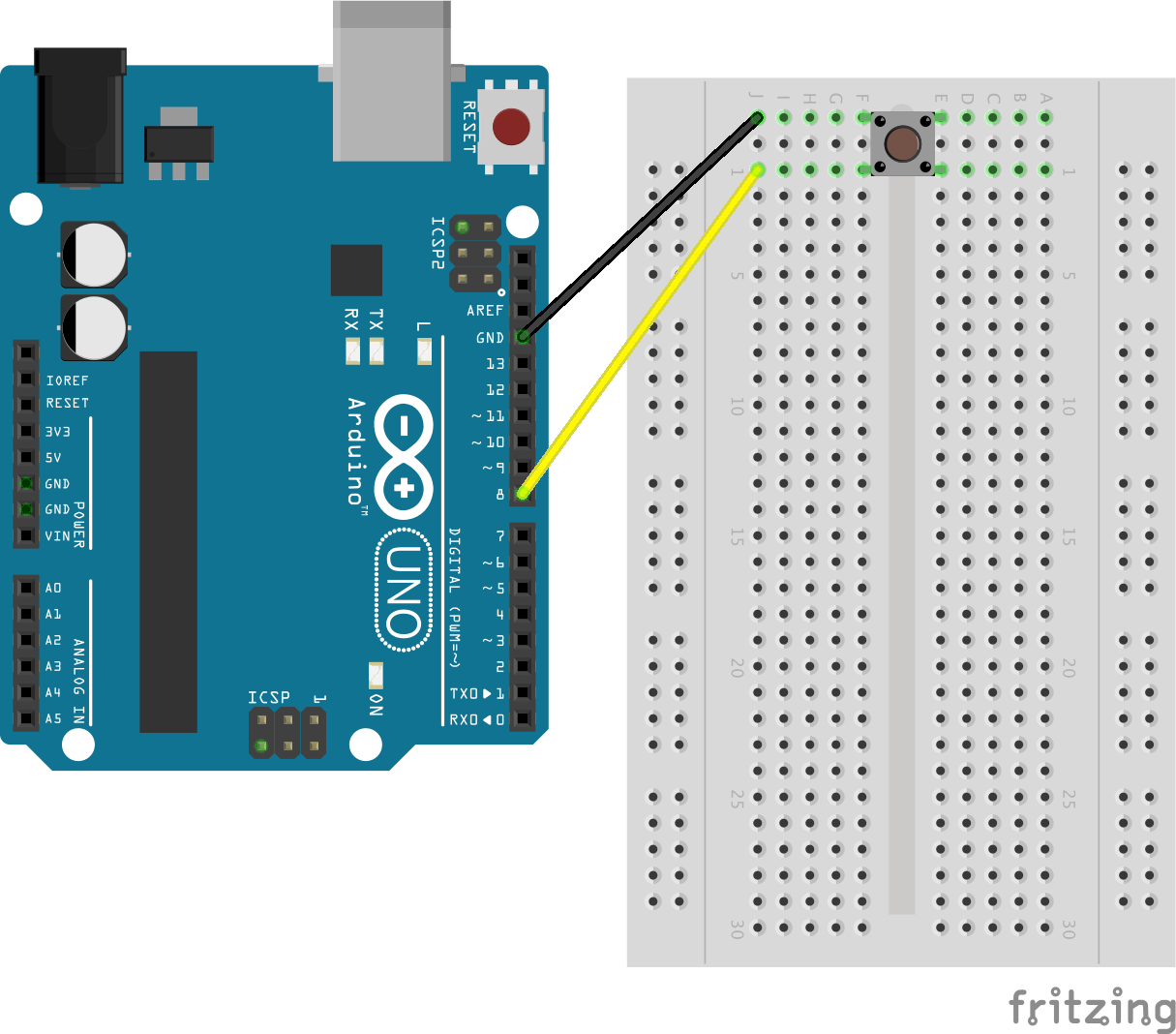

Before writing your actual code, write a simple program to use the serial monitor to display the value read on the analog input for each different button press.
ARDUINO BUTTON CODE
You will need to set up the range in your code for each push button and the values you use can be worked out in three different ways. A value may be right on the limit between 10 so it will be measured as 1012 when the resistor or room temperature is cold but 1013 when it is warmer. We use a range rather than an absolute value because the analog input and resistors are very sensitive to external influences such as temperature. The statements required to check which button is pressed are slightly more complicated than with digital IO.Įssentially your Arduino will read a value between on the analog pin and will need to compare this value to a particular range in order to identify which button has been pressed.

You can already see that the code is much simpler using the analog input as you are not required to define and set up your IO for analog pins. PinMode(input5Pin, INPUT) // declare push button inputsįor(int i=3 i=1009 & buttonValue=999 & buttonValue=984 & buttonValue=953 & buttonValue=910 & buttonValue<=951)ĭigitalWrite(ledPin, LOW) //Switch the LED off if button is not pressed Int input5Pin = 7 // define push button input pins I have created a function which runs through the input checking code to avoid code duplication, follow this link if you’d like to read up more on using functions to simplify your Arduino code and make it more efficient.

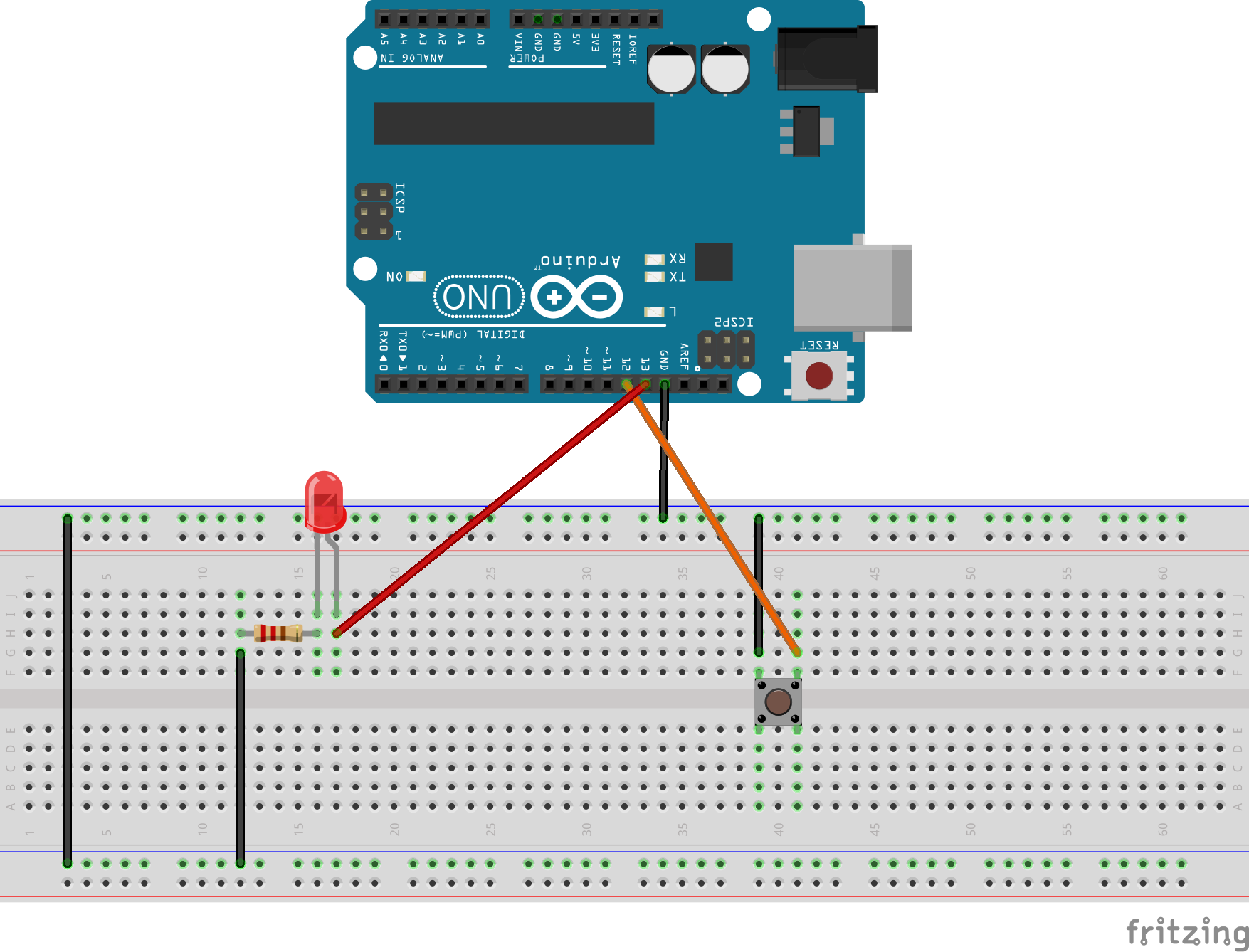
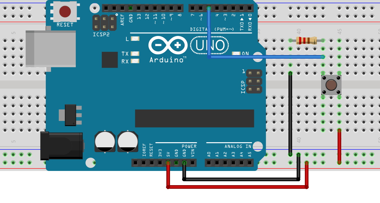
Let’s now have a look at the code required to turn off the LED on Pin 13 if any of the push buttons are pushed. Try connecting up 5 push buttons and 5 2K resistors each connected to a separate IO pin on your Arduino as shown in the breadboard diagram below. If you’re specifically looking to connect a 4×4 keypad to a single Arduino input, take a look at the linked guide as they are typically wired a little differently to the below example and you’ll need to make some adjustments to your circuit. Let have a look at how we’d connect 5 push buttons using the standard digital IO method. A 10 digit keypad for example uses 12 inputs, 10 digits from 0 to 9 and then a further two for the * and # keys. The problem comes in when you need to use multiple buttons. Connect Multiple Push Buttons To Multiple Digital IO Pins If (pushed = HIGH) // check if the input is HIGHĭigitalWrite(ledPin, LOW) // turn LED OFFĭigitalWrite(ledPin, HIGH) // turn LED ONĪs you can see from the above connection diagram and code, it is quite simple to connect a single push button and use it to drive other IO or settings in the code on your Arduino. Int pushed = digitalRead(inputPin) // read input value PinMode(inputPin, INPUT) // declare push button as input PinMode(ledPin, OUTPUT) // declare LED as output Int inputPin = 7 // choose input pin 7 for the push button Int ledPin = 13 // choose the pin for the LED Now lets have a look at the code required to turn the LED on Pin 13 off when the button is pushed. To start off, lets look at connecting a single push button to a single digital input pin, Pin 7, on your Arduino and use it to turn off the built in LED on Pin 13.Ĭonnect your push button and 2K resistor as shown in the breadboard diagram below.

In this tutorial we’re going to be looking at how you can set up a large number of buttons to run on a single Arduino analog input, using resistors to differentiate between buttons. The most commonly used Arduino board, the Arduino Uno, only has 12 available digital IO pins, so you may find yourself quickly running out of available pins on larger projects or projects requiring a number of buttons or a keypad.


 0 kommentar(er)
